Celebrating the 76th anniversary of the founding of the People’s Republic of China and the Mid Autumn Festival!
Wishing all Chinese around the world a happy holiday!
01 Advantages of Ceramic BladesHard alloy cutting tools encounter...
Dry machining is one of the important development trends...
~Abandoning the complexity of multiple cutting tools, only one...
Wishing all Chinese around the world a happy holiday!

01 Advantages of Ceramic Blades
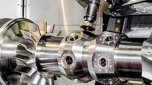
Hard alloy cutting tools encounter challenges when processing HRSA high-temperature alloys, and ceramic blade materials have become a powerful alternative. Whether it is turning or milling high-temperature alloys, Sialon and whisker reinforced ceramics have demonstrated their excellent applicability. It is worth mentioning that these ceramic materials perform particularly well when facing high-temperature materials such as Inconel alloy, which is commonly used in high-temperature environments for aircraft engines and energy production.
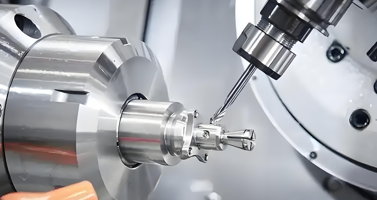
◇ Differences between milling and turning
Although ceramic materials have strong thermal hardening and low reactivity to workpiece materials, their strength and toughness are relatively low. Therefore, high rigidity methods are required during the processing to reduce vibration. In order to ensure the machining effect, the tool overhang should be minimized as much as possible, and the smooth insertion and retraction of the tool should be ensured. Meanwhile, full groove milling should be avoided during milling to fully utilize the advantages of ceramic materials.
Compared with ceramic turning, milling process presents some significant differences. When turning, the cutting speed is usually controlled within about 300 m/min; The speed of milling tools may be as high as 1000 m/min. In addition, ceramic turning requires continuous and high flow of coolant to dissipate heat; During the milling process, in order to avoid thermal stress, there is no need to use coolant at all.

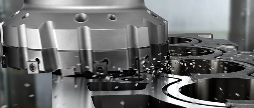
◇ High productivity of ceramic milling
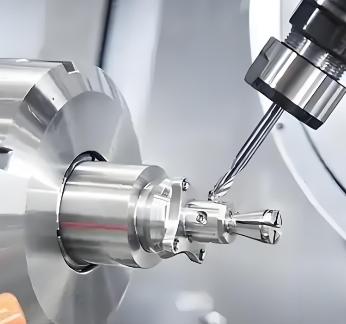
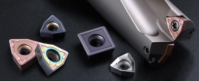
When choosing cutting tools, circular inserts are the ideal choice for turning and milling ceramics. To reduce groove wear, it is recommended to use a lower cutting depth and achieve a small main deviation angle. Meanwhile, during the milling process, a relatively low feed rate (compared to hard alloys) should be followed to achieve higher cutting speeds. In this way, the high temperature generated around the cutting area will enhance the cutting effect and promote the efficient removal of hot small chips. In addition, surface milling performs better in ceramic milling compared to edge milling and waterline milling.
The use of ceramics for milling, especially in the application of ISO S materials in aerospace engines, has demonstrated significant high productivity advantages. During the milling process, it is recommended to use forward milling for positive rake angle inserts, while reverse milling is suitable for negative rake angle slots. However, it should be noted that reverse milling may result in thick chips at the outlet. Through a series of optimization measures, the maximum speed capability of ceramic cutting tools has been significantly improved, thus meeting the high requirements for metal removal rate in harsh HRSA high-temperature alloy applications.
02 Milling parameter optimization
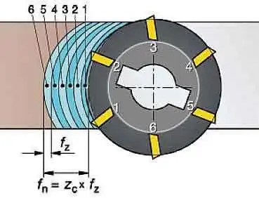
Reasonable feed rate per tooth is crucial for improving productivity and ensuring machining quality during the milling process.
◇ The importance of feed rate per tooth
In milling, the selection of feed rate per tooth is crucial. It not only affects processing efficiency, but also has a profound impact on processing quality. We must carefully choose the feed rate for each tooth based on different processing materials and specific requirements to ensure the smooth progress of the machining process. By optimizing tool design and cutting parameters, we can achieve efficient milling to meet the demanding application requirements of high-end fields such as aerospace engines.

◇ Workbench provides cutting depth
In the milling process, the feed rate (vf, in mm/min) of the worktable is an important parameter. Usually, it can be adjusted within the range of 600 to 2000mm/min, and the specific value depends on various factors such as the processing material, tool type, and required processing quality. Meanwhile, the cutting depth (ap, in millimeters) is also one of the key factors affecting the machining effect. By adjusting these parameters reasonably, we can achieve efficient and high-quality milling processing.

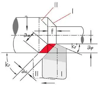
◇ Performance comparison and benefits
In milling operations, the feed rate of the worktable is interrelated with the cutting depth. The feed rate determines the distance that the tool moves per unit time, while the cutting depth reflects the depth at which the tool cuts into the workpiece during each cutting. These two factors jointly affect the efficiency and accuracy of processing. By reasonably matching the feed rate and cutting depth, we can achieve ideal machining results.
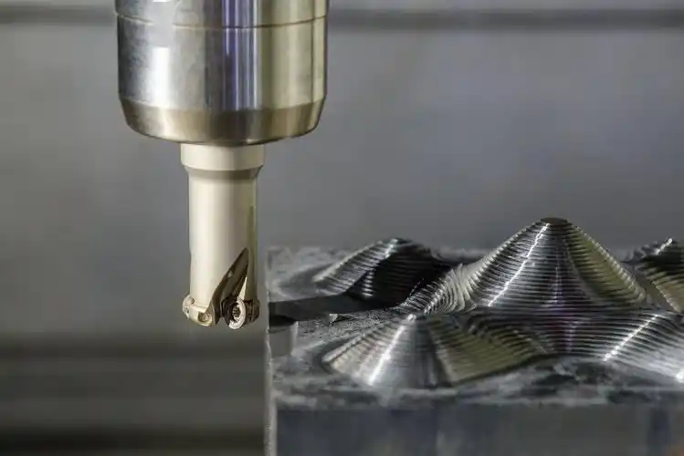
In the milling process, cutting width is a key parameter. When the cutting width is 1.5mm, we observed a significant increase in metal removal rate, from the original 19.3cm ³/min to 132.3cm ³/min. This improvement has brought significant benefits, saving a total of 42 hours of cutting time per year and increasing productivity by up to 469%. This result fully demonstrates the importance of optimizing cutting width in improving machining efficiency and saving time.
Dry machining is one of the important development trends in future metal cutting, which refers to a machining method that does not use or uses very little cutting fluid during the machining process. Its core goal is to reduce the dependence on cutting fluid, lower production costs and environmental burdens, while improving machining efficiency.
The key to this technology lies in tool design and material optimization. Cutting tools need to take into account geometric shape, high-temperature resistant materials, and coating technology: geometric shape needs to reduce friction and cutting heat to ensure smooth chip removal; The cutting tool material needs to have heat resistance and wear resistance, commonly using ultra-fine hard alloys, ceramics, etc; Coating technology reduces friction through insulation and solid lubrication, such as TiAIN coating, which is suitable for high-speed dry processing due to its strong oxidation resistance.
The development of dry processing stems from the emphasis on environmental protection and cost control needs of industrialized countries. The cost of cutting fluid treatment accounts for a relatively high proportion of the total cost of traditional machining, with statistics from the United States showing that it accounts for 14% -16%. Research has shown that if 20% of cutting is done using dry machining, the total cost can be reduced by 1.6%. With the advancement of high-temperature resistant materials and coating technology, dry processing has gradually become a feasible solution in the field of mechanical manufacturing.
One of the future trends in metal cutting: dry machining
Dry machining is one of the future trends in the development of metal cutting. In recent years, especially in industrialized countries, dry cutting has been highly valued. In order to implement environmental protection policies, efforts have been made to research, develop, and implement this new processing method. Cutting fluid plays a good role in reducing cutting temperature during operation, and is also beneficial for chip breaking and removal. However, there are also some problems, such as the use, storage, cleaning, and disposal of coolant, which are very complicated and costly. The harm of cutting fluid to the environment and the health of operators has always been limited in its use. The treatment of cutting fluid is also uneconomical, and these costs are often underestimated as they are included in indirect expenses. According to statistics from American companies, cutting fluid accounts for 14% -16% of the total cost in centralized coolant machining systems, while tool costs only account for 2% -4%. It is predicted that if 20% of cutting processes adopt dry machining, the total manufacturing cost can be reduced by 1.6%. Therefore, the future direction of machining is to use as little cutting fluid as possible, high-temperature resistant cutting materials and coatings, making dry machining possible in the field of mechanical manufacturing.
Tool Design
When designing cutting tools, it is always necessary to consider the balance between geometric shape, tool material, and coating, and it is impossible to use only the appropriate tool material for dry machining; Alternatively, only the coating method can transform traditional cutting tools into dry machining tools. In traditional cutting, various machining methods have different requirements for tool design. Dry machining tools must meet the following conditions: heat-resistant and wear-resistant tool materials, friction coefficient between chips and tools should be as small as possible, tool shape should ensure smooth chip removal, easy heat dissipation, high strength and impact toughness.
The design of dry machining tools must consider three aspects:
Coating. One of the reasons why cutting fluid can be omitted in today’s cutting process is coating, which reduces temperature shock by suppressing heat conduction from the cutting zone to the blade. Therefore, tool materials can be treated with coatings to achieve “solid lubrication” and reduce friction and adhesion. The tool absorbs less heat and can withstand higher cutting temperatures. Coatings have several functions in dry machining: isolating the tool from the cutting material, reducing friction, and insulation. Dry machining tools are usually coated and play an important role in tool performance. TiAIN coating has excellent heat resistance and high temperature performance. Compared with TiN and TiCN, the addition of AI greatly improves the anti-oxidation performance of cutting tools, making it very suitable for high-speed machining and dry machining. Its performance is four times better than TiC in high-temperature continuous cutting.
Geometric shape. Thermal effect is a fundamental issue in dry processing. When designing cutting tools, it is necessary to consider minimizing the possibility of heat generation at the beginning of machining, so cutting force and friction must be low. The additional problem with deep hole machining tools is that it is difficult to remove chips, so tool design must ensure a good chip removal effect. In the case of very low machining force, the design principle is to have a large rake angle and a large roundness cutting angle.
Tool material. The most important aspect of cutting materials during dry machining is high temperature resistance. If a large front angle is necessary, high hardness is also necessary. At present, the tool materials suitable for dry machining include ultrafine particle hard alloys CBN、PCD、 Ceramics and metal ceramics, etc.
~Abandoning the complexity of multiple cutting tools, only one milling tool is needed to improve aluminum material processing~
The automotive industry is facing a dilemma regarding “weight”. For example, the so-called light vehicles produced in the United States in 2017 had an average weight of 4044 pounds – so they don’t always live up to their name. New components and technologies have increased the weight of vehicles, but at the same time, environmental considerations require manufacturers to find ways to reduce weight. As a lightweight material, aluminum metal can solve this problem, but its milling and processing face challenges. In this article, Eduardo Debone, the global manager of Sandvik Coromant Automotive, a leading global metal cutting company, explains how to overcome difficulties with a single process milling cutter.
Aluminum metal will always be regarded as a material that can ‘fulfill the dream of flying’. The application of aluminum materials in the aviation field even predates the birth of the first aircraft in the late 1800s, namely Count Ferdinand Zeppelin’s famous aluminum framed airship of the same name, the Zeppelin airship. The lightweight characteristics of aluminum materials have made them still popular to this day. For example, its application in automotive engines can help significantly reduce vehicle weight and save fuel
For example, in the field of transportation, the power system of a European passenger car typically contains approximately 80 kilograms of aluminum material, making components such as the engine and gearbox the preferred weight reduction measures. Given the increasing popularity of aluminum materials, machine tool manufacturers require specialized cutting tool solutions to make aluminum metal the preferred material for workpieces.
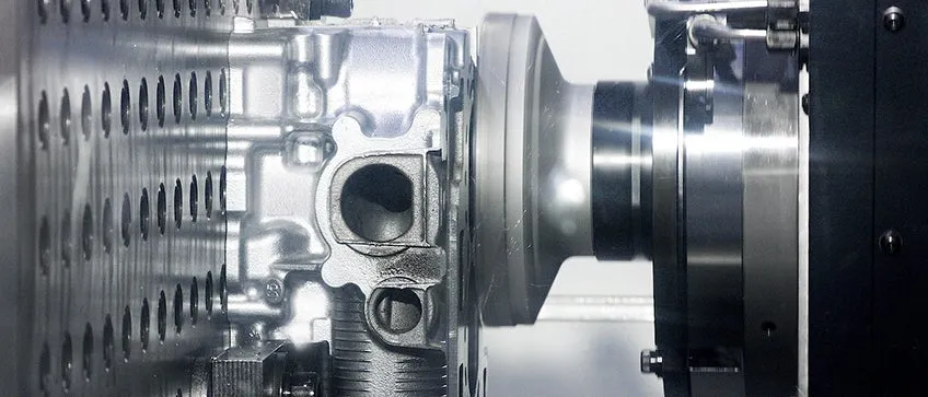
▲ Part complexity
The cylinder block is the main component of a vehicle engine, responsible for accommodating several moving parts that work together to generate the power required for vehicle movement. For many years, cylinder blocks have been made of cast iron materials, but nowadays passenger cars generally choose aluminum alloy materials to reduce weight.
In the production of automotive parts, the manufacturing of cylinder blocks involves the largest number of machine tools, the process flow is often complex, and the allowable tolerance range is small. The rough and precision machining of some key and complex automotive components, such as cylinder blocks, is an expensive and time-consuming process. The entire process requires the use of several different cutting tools, which means an increase in the frequency of fixture adjustment and the need for more coolant to reduce the heat generated by increased friction.
The cylinder head of the engine is also a critical component, often made of aluminum material. The cylinder head is responsible for delivering air and fuel to the combustion chamber; Meanwhile, due to its location at the top of the cylinder block, it is also responsible for accommodating various components such as valves, spark plugs, and fuel injectors. Like the cylinder block, the cylinder head also requires complex and precise high-quality machining.
Indeed, aluminum material is lighter than cast iron material, but at the same time it is much softer. Therefore, poor surface quality of workpieces, the generation of burrs, and uneven tool wear are common phenomena. So, how can car manufacturers overcome these challenges, shorten production cycles, improve surface quality, and save costs.

▲ Single process solution with ‘one sequence in place.
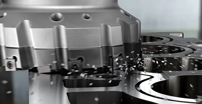
As an expert in the field of metal cutting, Sandvik Coromant has discovered that the essence of innovation lies in simplicity. Replacing multiple cutting tools with a single process solution for surface milling can easily solve many difficult problems in aluminum material processing. The so-called single process solution uses multifunctional milling tools, which means that the same tool can provide both rough and precision machining capabilities, thereby reducing the cutting force on aluminum materials and achieving higher quality machining results.
Sandvik Coromant’s aluminum material processing solutions include several unique patented tool designs that enable fault free, precise, and burr free milling. This includes our M5C90 aluminum milling cutter, which belongs to the M5 product series and is specifically used for rough and fine surface milling of cylinder heads, cylinder blocks, and all aluminum components. It is recommended for large cutting width milling and is not suitable for thin-walled components. This tool can complete the entire process from rough machining to precision machining in one sequence.
It is crucial that the tool can complete the entire milling process from coarse to fine with just one pass, and in many cases, the milling depth can reach up to six millimeters. We have witnessed significant results: tool life has been extended by up to five times, and production cycles have been shortened by up to 200%.

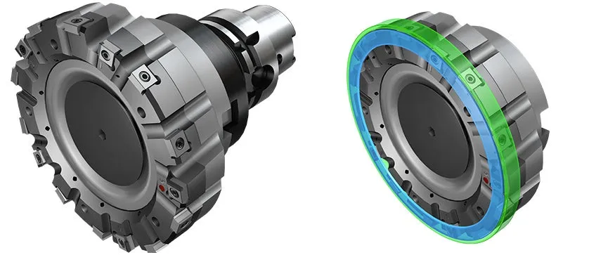
A key feature of the M5 series cutting tools is their progressive technology. A series of precise and durable polycrystalline diamond (PCD) blades are arranged in a circular pattern, gradually and minimally removing workpiece materials layer by layer, including axial and radial directions. In addition, the last tooth of the tool is designed with a wiper polished blade to ensure excellent surface quality and flatness. The position of the wiper polishing blade and other blades is fixed, thus eliminating the complex and time-consuming tool adjustment process. Although the entire manufacturing process of an automotive aluminum component requires several cutting tools, this multifunctional solution frees the aluminum material from bearing a lot of cutting forces during the machining process.
As part of the ongoing pursuit of environmental performance in the automotive industry, selecting appropriate materials will become an indispensable part of vehicle weight reduction strategies. At the same time, tools such as M5C90 aluminum material milling cutters provide manufacturers with a simpler processing method that can meet various processing requirements for complex aluminum materials. From this perspective, perhaps aluminum materials can naturally become a good solution to the “weight” dilemma in the automotive industry.
The characteristics of the tungsten carbide material itself determine the importance of the safe operation of the tungsten carbide foot cutting machine blade. Before installing the blade, take protective measures to avoid unnecessary personal and property losses caused by the falling of the blade.
A. Hearing inspection: When installing the blade, please carefully lift the blade with the index finger of your right hand and make the blade hang in the air, then gently tap the blade body with a wooden hammer, and listen to the sound on the blade body with your side ears. For example, if the blade emits a dullness, experience has proved that the blade body has often been damaged by external force and has cracks and damages. This kind of blade shall be prohibited immediately. Do not use the foot cutter blade that emits voiced sound!
B. Blade installation:
a. Before installing the blade, please carefully clean the dust, chips and other sundries on the mounting surface of the rotary bearing of the foot cutting machine in advance to keep the bearing mounting surface and the foot cutting machine clean.
b. Carefully and stably place the blade on the mounting surface of the bearing, and manually rotate the foot cutter bearing to align it with the blade center automatically.
c. 2. Install the cutter block on the foot cutter blade and align the bolt hole with the bolt hole on the foot cutter bearing.
d. 3. Install the hexagonal socket bolts, and use the hexagonal socket wrench to tighten the screws to firmly install the blade on the bearing.
e. 4. The blade shall be free of looseness and deflection after installation.
C. Safety protection: After the blade is installed, before starting the foot cutting machine, the safety protective cover and other protective devices on the foot cutting machine must be installed in place and play a real role in protection (the blade working room on the foot cutting machine should be equipped with safety baffles, steel plates, rubber and other protective layers).
D. Running speed: the working speed of the foot cutting machine shall be limited to 4500 rpm. It is strictly forbidden to operate the foot cutting machine beyond the speed limit!
E. Test machine: After the blade is installed, it should run for 5 minutes without load, and carefully observe and listen to the operating condition of the foot cutting machine. It is absolutely not allowed to have obvious looseness, vibration and other abnormal sounds (such as obvious axial and end face runout of the foot cutting machine bearing). In case of any abnormal phenomenon, stop the vehicle immediately and ask professional maintenance personnel to check the cause of the fault. After confirming that the fault is completely eliminated and normal, it can be used.
F. In the cutting process, please push the PCB to be cut at a constant speed, and do not push the PCB too fast. When the circuit board collides with the blade violently, the blade will be damaged (collapse and crack), and even serious safety accidents will occur.
G. Storage method of blade: It is forbidden to write or mark on the blade with an electric engraving pen or other scratch methods to prevent damage to the blade body. The blade of the foot cutting machine blade is extremely sharp, but very fragile. To avoid injury to personnel or accidental damage to the blade, do not touch people or other hard metal objects with the blade. The blades to be used shall be properly kept and stored by special personnel, and shall not be put aside randomly to prevent the blades from being damaged or causing accidents.
The premise of production efficiency is also safe operation. The cutting operator must follow the relevant use requirements to make the foot cutter blade work safely on the foot cutter.
CIMT2025, as the largest professional event for machine tools in the world in the past decade, has an exhibition area of 310000 square meters and a total of 345864 visitors. Renowned machine tool companies from around the world brought their latest technologies and products to the venue.
Cutting tools, as the “teeth of industry”, performed very well at this exhibition. Not only have domestic cutting tool companies emerged like mushrooms after rain, but some overseas enterprises have also returned with their latest products, concepts, and models, jointly showcasing innovative technologies and application achievements in multiple segmented fields to the audience, and depicting the future development direction of cutting tools for everyone.
We will now introduce some innovative technological achievements and application examples in the field of cutting tools at this exhibition.
1、 Technological innovation achievements
1)Cutting tools are moving from product provision to value services
The cutting tool industry has transitioned from selling a single product to providing users with comprehensive solutions, that is, the era of providing value services to users. On the basis of in-depth exploration of user needs, domestic tool exhibitors exhibited comprehensive solutions in different fields at this exhibition. Domestic enterprises such as Zhuzuan, Jinlu, Tooling Institute, Sentai Inge, Ouke Yi, Huarui, and Aoketai exhibited metal cutting overall solutions for different industries. Ouke Yi also proposed a customized overall supporting solution of “tool general contracting+intelligent warehousing”; Zheng Zuan and REGO-FIX exhibited a comprehensive solution for tool loading and unloading.
In short, it is evident from this exhibition that various tool companies are gradually transforming from traditional tool product suppliers to service providers that provide value to users. They are deeply exploring and refining different customer needs, providing optimized solutions and value services. I hope to communicate and integrate with each other through the exhibition platform, learn from each other’s strengths and weaknesses, and jointly provide efficient machining solutions for cutting and processing users, provide value services for users, and thus realize our own value.
2)Innovation in material technology
The new SNC805 and SPC810 products launched by Chloe for aerospace component processing both use ultrafine grained substrates to minimize thermal cracking at high temperatures and prevent blade breakage. APS05A in the Dragon series launched by Arno is a low cobalt matrix with ultrafine particles, which has excellent wear resistance and is the preferred material for difficult to machine materials. It can also be used for precision machining of stainless steel, quenched materials, and cast iron materials. The CM7115A and CA5105 from Changying Hard Science are both made of ultra-fine grain matrix with strong wear resistance, and are respectively used for turning and milling difficult to machine materials. Some foreign brands at this exhibition have launched applications of pure ceramic milling tools and high-speed milling of high-temperature alloys and cast iron.
The “Silver Sparrow” series of grades brought by Xiamen Jinlu as GEFOTECH ® The further upgrading of technology has achieved significant breakthroughs in tool substrate, coating, and surface edge treatment, forming a new GS * 71 series grade, which solves the problems of easy chip adhesion, abnormal blade breakage, and short service life in titanium alloy processing. The “Silver Sparrow” series titanium alloy processing end mill ST300, launched at this exhibition, optimizes and innovates cutting tools for processing problems. It can suppress adverse resonance and improve chip removal performance as a whole. By matching with a new titanium alloy processing special grade, it can improve wear resistance and tool life, effectively solving customer problems.
3)Innovation in Coating Technology
Composite CVD coated blades have become the mainstream trend, and many tool companies have launched their own dual color CVD coated blades. The new products of conventional CVD coatings often highlight the optimization of the growth direction of Al2O3 crystal structure, such as Sumitomo’s AC8115P for high-speed steel turning, which uses crystal orientation control technology to improve wear resistance, and Mitsubishi’s MC5100 series for cast iron turning, which uses “super” nanostructure technology to improve wear resistance. There are two technological directions for PVD coatings: one is to search for new coating systems, or to combine two existing coatings and add them as functional layers to products; Another approach is to dope or nano multilayer modulate the coating on the existing basis. Whether it is CVD or PVD coating, the goal is to improve the surface quality of the coating, using new HiPIMS technology, smooth surface treatment or coating post-treatment technology to improve surface smoothness and prevent the formation of chip tumors and chipping.
The Pangu series PG8000 products based on low-pressure CVD coating technology launched by Zhuzuan Cutting Tools focus on efficient processing of difficult to machine materials and high hardness materials. This series combines advanced coating technology with precision groove design, and its main technical features and market applications include: (1) coating process optimization. The PG8000 product adopts a high hardness substrate combined with nano superlattice structure coating and ultra smooth surface treatment technology, significantly improving wear resistance and high temperature resistance, and is suitable for processing materials such as high-temperature alloys and heat-resistant cast steel. The design of lattice heterogeneous coating further enhances high-temperature oxidation resistance and coating hardness, and improves surface smoothness and reduces cutting adhesion through coating pre-treatment and post-treatment processes. (2) Groove type and tool compatibility. Provide turning groove types such as NF, NGF, SNR, covering scenarios from precision machining to efficient rough machining; Milling tools such as FMA12 and EMP09 are suitable for complex processes such as face milling, shoulder milling, and profile milling. New precision turning groove QF and milling series EMP08 and XMR12 have been added to optimize cutting smoothness and machining efficiency, meeting the high-precision machining needs of aerospace and other industries.
4)Product structure innovation
This year’s product structure innovation is constantly emerging, and various manufacturing enterprises have developed products with different structures and characteristics based on the constantly segmented user needs. The FP slot series launched by Kenner adopts a unique single screw wedge clamping system, where the blades are compressed by wedges instead of traditional screw holes, achieving a hole free design. Wedge block compression and large-area contact increase rigidity by 20%, solving the problem of easy loosening in traditional screw fixation, suitable for heavy-duty processing of cast iron materials. Teguk has launched a turning tool with a 70 degree tip angle, which can balance edge strength and avoid interference, providing new ideas for solving some machining problems.
The ZBMT series imitation machining blades with a 25 ° sharp edge angle from Kyocera Corporation in Japan adopt a special structure of 2-point locking blades to prevent blade displacement. The 3D chip breaking groove extends to the vicinity of the cutting edge, reducing chip breaking problems during micro depth machining and effectively controlling chips in narrow machining spaces. In response to more requirements for machining and contouring, the ZBMT series blades have their front end machined to 15 ° on the basis of a 25 ° blade tip angle, which can effectively avoid interference and meet various machining purposes. The tool tip radius is only 0.4mm and adopts a dual cutting edge design that can be used for both forward and reverse machining.
5)Innovation in chip control technology
Chip control technology has always been a key challenge in automated production, and Mitsubishi has launched a specialized product based on low-frequency vibration cutting (LFV). Low frequency vibration technology is achieved by vibrating the servo shaft in the cutting direction, synchronizing the vibration with the spindle rotation while cutting. This results in the intermittent discharge of small and fragmented chips, thereby solving problems caused by chip entanglement during machining. This is particularly important in the processing of difficult to machine materials and automatic production lines.
Isca brings a brand new design of triangular blade LOGIQ-6-TUN, providing a semi precision machining and precision machining turning solution that can achieve high surface quality and cost-effectiveness. This double-sided blade has a cutting edge tip angle of 55 ° and a positive rake angle profile, with 6 rotatable cutting edges. It is an alternative to DCMT type standard ISO blades (with only 2 cutting edges). Another important advantage of LOGIQ-6-TUN blades is that they can be easily installed on turning tools equipped with triangular TNMG blades. At the same time, the special chip breaking groove design of LOGIQ-6-TUN blade enhances the chip control ability of the blade when processing different materials, and the chip control technology of the blade is precisely one of the foundations of intelligent manufacturing.
6)Product technology extension
Tool manufacturing enterprises utilize mature technologies accumulated over many years to extend to other application fields, developing new products, processes, and technologies. Developing precision hydraulic expansion fixtures for gear machining using hydraulic tool holder clamping technology, and extending them to robot precision reducer machining and assembly fixtures; A high-precision VSD gear honing and grinding wheel dresser developed using PCD tool precision manufacturing technology, with a shape accuracy of up to 0.001mm; a zero point positioning fixture developed using PSC triangular pyramid positioning interface technology, etc.
The high-performance angle head showcased by Sentai Inge relies on years of precision and high rigidity positioning interface design and manufacturing advantages, innovatively adopts pre service design theory, forward research and development, and is equipped with imported gears and bearings to ensure high precision, high torque, low noise, small temperature rise, and long life of the angle head. The successful breakthrough of this technological bottleneck not only fills the gap in high-performance angle heads in China, but also extends the technology to machine tool accessory heads and CNC swing head products, developing products comparable to international first-line brands and helping to improve the performance of domestic industrial mother machines.
7)Innovation in Intelligent Cutting Tool Technology
In terms of intelligence, the Internet of Things and AI technology are deeply integrated into the full lifecycle management of cutting tools. For example, the intelligent tool holder developed by Zhuzhou Diamond can monitor wear in real-time (with an accuracy of ± 5 μ m), and the Mitsubishi MAISART system optimizes cutting parameters through machine learning, reducing energy consumption by 18%.
The KomTronic U-axis system launched by Gaomaite is an innovative solution that integrates mechatronics and intelligent control technology, focusing on improving the accuracy and efficiency of complex part machining. Its product has the following two advantages: (1) radial precision motion control. The U-axis is driven by a servo motor to achieve precise displacement adjustment of the tool along the radial direction, with a minimum accuracy of 0.001mm. It also integrates an electronic compensation system (such as the MO40/MO42 series), which supports real-time tool adjustment on a digital display screen and automatically corrects thermal deformation errors during the machining process. (2) Dynamic processing adaptability. Adopting inductive non-contact energy transmission technology, the stator components on the spindle are wirelessly connected to the U-head components to ensure stable signal transmission during high-speed rotation. Built in sensors collect real-time cutting force, temperature, and other parameters through KomTronic ® The intelligent system dynamically adjusts the tool path to reduce vibration interference. It can be used in application scenarios such as complex contour machining and high-precision synchronous machining.
2、 Characteristics of Industry Development
Looking back at the entire CIMT2025, well-known domestic and foreign tool companies and tool products were all present, competing on the same stage with advanced technology, advanced processes, advanced products, and advanced concepts, presenting the following characteristics:
1)The technological gap between domestic and foreign products is gradually narrowing
In recent years, the cutting tool industry has entered a period of stable development. There have been no cross era inventions in product technology, only continuous optimization and innovation in details, which has left enough opportunities for the rapidly developing domestic cutting tool industry to catch up. In terms of tool materials, except for some difficult to machine materials with slight differences, domestic tools can basically meet the requirements of general material processing, reaching the level of “running parallel” with foreign tools. In terms of tool manufacturing technology, with the introduction of advanced process equipment and the upgrading of domestic process equipment, the tool manufacturing process is basically synchronized with foreign tools. The 3D printing technology of cutting tools exhibited at this exhibition has also been widely used in China. In terms of product technology, with the continuous strengthening of R&D investment by domestic enterprises, some key bottleneck technologies of cutting tools have been overcome one after another, and product technology can reach the international advanced level, such as damping and vibration reducing cutting tools. Multiple domestic enterprises have exhibited such products. However, compared to foreign countries, electromechanical products are still slightly lagging behind.
2)The cutting tool industry has entered the era of great integration
The cutting tool market has transitioned from extensive product sales to an era of meticulous cultivation for users. In the current market environment, customers have become extremely valuable and rare resources. Once trust is established with customers, pursuing the maximization of customer resource utilization becomes a common goal for enterprises. However, it is almost impossible for a company to fully rely on its own products to meet customer needs. It requires strong supply chain resources, integrating industry process equipment, advantageous products, and promotion platforms through its own technological advantages to create comprehensive services for users. At this exhibition, both Senla Tianshi Company and Germany’s Sunk Company showcased the iTENDO ² intelligent knife handle; Meanwhile, Kenner&Co in the United States utilized its booth to hold a technology seminar called “Gathering Momentum and Moving New” with numerous partners, jointly providing products and services to customers.
Wishing all Chinese around the world a happy holiday!
01 Advantages of Ceramic BladesHard alloy cutting tools encounter...
Dry machining is one of the important development trends...
~Abandoning the complexity of multiple cutting tools, only one...
FUJI Tools was founded in 1992 with a business policy dedicated to CNC machining center peripheral tools and cutting tools. In recent years, the company has invested more resources to establish a comprehensive operating environment and advanced manufacturing equipment in response to the cutting market demand, providing higher product quality and improved processing efficiency for mechanical processing industry workers.
Xingtan , Shunde ,Foshan City,Guangdong,China 528303
fujicn@jsh-fujitools.com
86-138 2276 9081